The VM600 turbine monitoring system for a million-unit nuclear power plant primarily measures and monitors relative shaft vibration, absolute bearing seat vibration, axial displacement of the turbine rotor relative to the thrust bearing, and rotor elongation relative to the turbine cylinder reference point.
Let's discuss the VM system.
1. Hardware
Vibro-Meter's VM600 series machine protection and monitoring system is based on a 19" x 6U frame and includes various components depending on the application. There are basically two types of systems:
Machine Protection System (MPS)
Condition Monitoring System (CMS)
MPS and CMS hardware can be integrated into the same frame.
The following details the hardware included in the MPS (see Figure 1).
1) The ABE 04 X frame structure (19" x 6U) comes in two types: ABE040 and ABE042. The difference lies in the mounting position of the brackets within the frame. 2) RPS 6U rack power supply unit
3) MPC 4 rack protection card
4) IOC 4T MPC 4 input/output card
5) AMC 8 analog monitoring card
6) IOC 8T AMC 8 input/output card

The MPC 4 and IOC 4T cards must be used in pairs; no card can be used individually. These cards are primarily used for vibration monitoring. Similarly, the AMC 8 and IOC 8 T cards must be used in pairs; these cards are primarily used for quasi-static parameters such as temperature, level, or flow.
A rack can contain:
Only one pair of MPC 4 / IOC 4 T cards
Only one pair of AMC 8 / IOC 8 T cards
A combination of one pair of MPC 4 / IOC 4 T and one pair of AMC 8 / IOC 8 T cards
Depending on the application, the following card types can also be installed in the rack:
7) RLC 16 Relay Card (16 relays) All of the above modules can be used to form a standalone MPS system, that is, a system not connected to a network. A networked MPS system, in addition to the above hardware, also includes the following hardware for the ABE 04 X frame:
8) CPUM CPU card
9) IOCN input/output card (matching the CPU M). Depending on the application requirements (regardless of whether the frame is a stand-alone or networked configuration), one or more of the following low-noise power supply components may be used outside the frame:
APF195 DC-DC converter
APF196 AC-DC converter
Any customer-supplied equivalent low-noise power supply unit
These devices must be used with GSI 1 XX galvanic isolation units, GSV safety barriers, and converters/proximitors with currents greater than 25 mA.
2. Software
One of the following software packages is required to configure the MPS:
1) MPS 1 Configuration Software
This software configures the MPC 4 and AMC 8 cards in the networked VM600 frame, which includes a CPU for control and communication. All cards in the frame can be configured in "oneshot" mode via Ethernet.
2) MPS 2 Configuration Software
This is an expanded version of the MPS 1 software package. In addition to providing all the functionality of MPS 1, MPS 2 software also includes MPC 4 and AMC 8 management, unit diagrams, and data trending.
3. MPS Communication Methods
The MPS system can be configured in a variety of ways, depending on the hardware installed in the ABE04X rack.
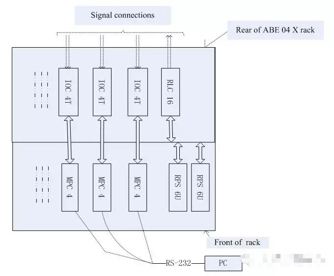
1) Figure 2-a below shows the simplest MPS configuration. This is a stand-alone rack. In this case, the MPC 4 or AMC 8 card in the rack must be configured using a personal computer via RS-232 communication, which is connected through the 9-pin connector on the front of the card.
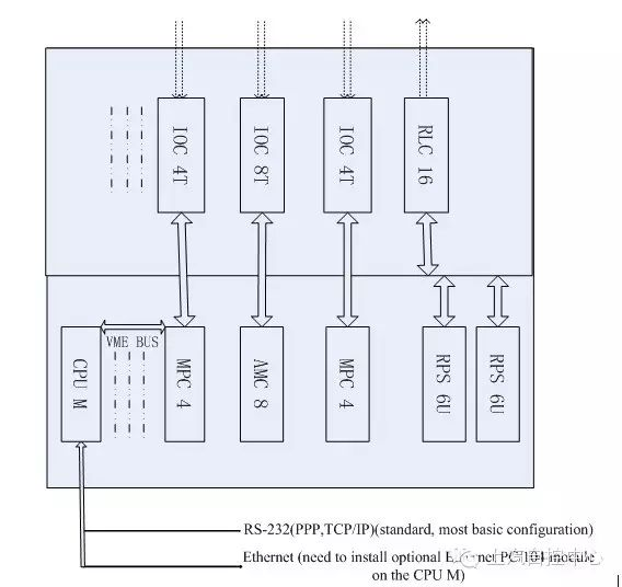
2) Figure 2-b shows a rack containing a CPU card (CPU M). The Ethernet connection between the personal computer and the MPS system is established through the front panel of the CPU M card. Communication between the CPU M and the MPC 4/IOC 4 T or AMC 8/IOC 8 T card is via the VME bus on the rack backplane.
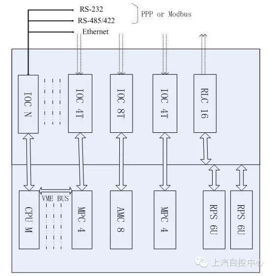
3) Figure 2-c shows a rack containing a CPU card (CPU M) and matching IOC N input/output cards. Ethernet connections are established between the personal computer and the MPS system via the IOC N card's backplane. Communication between the CPU M and the MPC 4/IOC 4 T or AMC8/IOC 8 T cards occurs via the VME bus on the rack's backplane.
4. MPS Monitored Parameters
The MPC 4 card in the MPS system can measure the following parameters:
Absolute vibration (shoe vibration)
Relative vibration (radial vibration measurement, including DC gap voltage measurement)
Absolute rotor vibration and rotor position (axial measurement)
Smax vector value (compliant with ISO 7919 standard)
Rotor eccentricity
Absolute and relative expansion (between rotor and stator)
Cylinder expansion
Displacement
Dynamic pressure
The AMC 8 card in the MPS system can measure the following parameters:
Temperature (thermocouples or RTD probes connected directly to the IOC 8 T card)
Any user-defined process variable, such as flow, level, or valve position. Other MPS system features include:
Hot-swappable MPC 4, IOC 4 T, AMC 8, IOC 8 T, and RLC16 cards. These cards can be inserted or removed without powering down the ABE04X frame.
Single-board configuration storage
Online modification of all parameters while the MPS is running
Real-time data processing available
Configurable internal power supply for transmitters
Built-in self-test (BITE) circuit
Hazardous bypass function
Alarm signal reset
Alarm multiplication or adaptive monitoring
Up to four inputs (measured vibration, dynamic pressure, etc.) can be connected to a single processing channel.